NERDS electronics course Phase 3 notes
January 11, 2017
At last night's meeting we delved again into the operation of simple amplifier circuits, looking at a triode vacuum-tube amplifier, basic bipolar junction transistor (BJT) amplifiers, and a type of field-effect transistor (FET) amplifier.
How basic amplifiers work in practice is based on how they are biased. We looked at how the simplest single-resistor base biasing scheme for bipolar junction transistor amplifiers deliver varying gain results, due to the fact that a bipolar transistor's beta varies from device to device, even in the same batch. Not so good.
The slightly more advanced voltage-divider technique for biasing BJT amplifier base circuits completely removes the effect of beta on overall gain in a common-emitter amplifier.
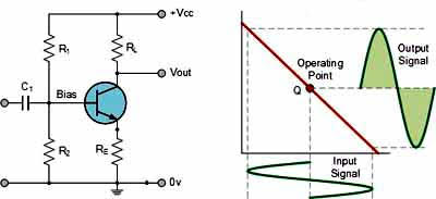
Here's a schematic of an NPN BJT amplifier, operating as a Class A amplifier. Note the use of R1 and R2 in series as a voltage divider to set the exact desired base-bias voltage point.
Recall how the output voltage-swing spans 360-degrees of operation, thanks to the fact the transistor is biased at a Q point in the middle of its characteristic curve. The transistor is never "off," so it has a poor efficiency rating -- based on allowable dissipation (heat) -- of about 30 percent.
This is dubbed a Class A amplifier. It is operating on the linear portion of its operating curve. As such, the output signal is a reasonable facsimile of the input sinewave, albeit 180-degrees out-of-phase. The output is essentially non-distorted. This would work well in the shack for a microphone or headphone amplifier, for example.
Now let's look at a Class B amplifier (diagram below), as touched on last night. In this simplified example there is a PNP transistor working in conjunction with the more common NPN type. The biasing components are not shown. However, note how each BJT conducts over only a 180 degree period. As such, the output is only half of the applied input sinewave.
However, with the use of an NPN device and a PNP device, each conducting over 180 degrees, you can re-assemble a complete 360 degree sinewave at the output.
This is called a complementary Class B amplifier block. Each BJT's output signal conducts only over 180 degrees, but they can add up to a full 360 degree output wave shape.
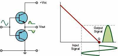
The use of two devices as shown comprises what's called a push-pull amplifier. Significantly, because each transistor only conducts over 180 degrees, it is essentially cooling off over the "other" 180 degrees. Class B amp's therefore typically have efficiency ratings of about 50 or 60 percent.
Now let's look at the simple typical Class C amplifier that we discussed. They're often used as RF amplifiers where non-linearity is not an issue, such as in the FM output stage of your 2-meter rig's transmitter circuit.
This example (below) uses a parallel (anti-resonant) LC resonant circuit as the collector load, instead of a resistor.
Recall from Phase 2, for a moment, that a parallel LC circuit, once energized, should transfer magnetic energy to the capacitor from the inductor, and then transfer electrostatic energy from the cap back to the inductor.
If L and C were pure and lossless, this resonant circuit, where Xl = Xc, would oscillate back and forth forever. No power would need to be applied from a external amplifier.
As such, we could theoretically conclude that the impedance of this parallel LC circuit was infinitely high (as opposed to the very low Z of a series-resonant LC circuit).
Too bad there are real-world losses, though, eh? The cap might have leakage and the inductor has resistance of its windings, and even the wiring connecting L and C has resistance.
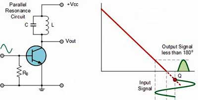
To continue, if we bias our BJT over a very non-linear portion of the characteristic transfer curve, the output signal would be a portion of the input sinewave. The BJT would conduct over something less than 180 degrees. This "pulse" can be used to poke energy into our parallel anti-resonant circuit, keeping it oscillating, regardless of losses! How cool is that?
Because the Class C amplifier's device isn't conducting most of the time (whether it be a tube, BJT or FET) it runs comparatively cool; it's efficiency can be high, perhaps 70 to 80 percent or so.
The Class C amplifier's pulse-like output is said to be distorted, but who cares if you're using that to keep the LC circuit in a flywheel state? The LC circuit's flywheel action will smooth out the pulses to some semblance of a sinewave. You could use that in a CW transmitter, for example, or perhaps in an FM circuit power-amp stage where linearity is not required. No good for SSB, though. SSB requires an inefficient linear RF amplifier.
Food for thought. CU at our Q&A review at 6:15-PM, prior to the NERDS meeting, on January 17th.
Vy 73, AI2Q, Alex